With the ever increasing pressure on emissions control, oxygen sensors have become a critical part of the engine management system and we are seeing a lot more of them being replaced due to tighter tolerances and specifications that will bring the engine light on if they are not working with those specification.
Unfortunately they are also right up there as one of the most mis-diagnosed parts in the engine management system because an oxygen sensor fault code does not always mean that the sensor itself is faulty, but may indicate other mechanical or electrical issues that the sensor is merely reporting, like air leaks, fuel pressure problems or catalytic convertors that are not working efficiently.
OK, so the basic function of the OXYGEN SENSOR, no matter what type it, is to give the ENGINE CONTROL MODULE an idea of what has happened with the combustion of the fuel and air mixture in the engine so it can make adjustments to try and keep the mixture as close as it can to complete combustion and reduce emissions.
SENSOR IDENTIFICATION
Sensors are mounted in the exhaust in different locations depending on the engine configuration and the exact purpose that the sensor is being used for.

Sensors that are used by the ECU for mixture control are always mounted before the catalytic convertor and sensors that are used to monitor if the catalytic convertor is working correctly are mounted after the Cat.
Identifying the correct sensor can sometimes be an issue as different vehicle manufactures can use different methods. The fault code should always tell you which sensor is logging the code, as in BANK1 SENSOR1,etc, but that sensor may not always be in the same position in the engine bay. BANK1 may be on the drivers side,passenger side or in an east-west configuration it may be the radiator side or the firewall side. The only thing you need to remember though is that no matter the configuration, BANK1 is always where CYLINDER1 is located.Identify CYLINDER1 and you will know which bank is which. The second part of the location is to let you know if the fault code relates to a pre-cat or post-cat sensor. SENSOR1 indicates pre-cat and SENSOR2 indicates post-cat. So a fault code P0141 (02 SENSOR HEATER CIRCUIT BANK1 SENSOR2) would indicate the the sensor for Bank2 after the cat is causing the code to log.
Some inline 4 cylinder engines can have a BANK1 and a BANK2 as well. The same rule still applies. BANK1 will be the sensor reading off CYLINDER 1. They may be paired up as CYLINDER1+4 and BANK2 may be for CYLINDERS 2+3.
PHYSICAL CHARACTERISTICS
The sensors themselves come in different styles so lets have a look at some of the major differences.
The most obvious difference is the number of wires on the sensor.1-2-3-4-5 and 6 wire sensors can be found in the pre-cat location and 4 wire sensors in the post-cat location. Some 4 wire and all 5 and 6 wire sensors are WIDE BAND sensors and I will talk about those on another day. We will stick with the NARROW BAND sensors at the moment. Narrow and Wide Band refers to the range in which the sensor is able to accurately sense the oxygen level in the exhaust and I will say more on this shortly.
1 wire sensors have a single wire that sends the signal back to the ECU.Now for any electrical circuit to work you need to have a complete circuit. i.e a POSITIVE and a NEGATIVE, so the sensor earth is made through the body of the sensor and then into the exhaust piping and onto the engine.
2 wire sensors have a signal wire and also a signal earth wire. the earth wire helps to reduce the risk of bad earths through the exhaust.
3 wire sensors have a signal wire and the other two wires are for the heater circuit. Again the signal earth is through the body of the sensor.
4 wire sensors have a signal wire and a signal earth wire and two wires for the heater circuit.
Oxygen sensors don't work very well until they a very hot. Over 350 degrees. So manufactures have added the heater circuit to the sensors so that they heat up more rapidly and the ECU can also have some control over keeping the sensor at the desired temperature. Un-heated sensors, 1 and 2 wires sensors, only get the heat transfer from the exhaust so take longer to heat up and also require a fair amount of exhaust gases to be flowing over the sensor to keep it hot enough to operate.
There are all sorts of variations on the exact design and look of the sensor from different tips, thread mounted or flange mounted, body diameter, internal construction variations but none of these have any great effect on how you diagnose the sensor so we don't need to get to bogged down with these.
One difference that can affect how you test a narrow band sensor is weather it is a ZIRCONIA or TITANIUM type sensor. This refers to the material that the sensing element is made from. Zirconia sensors work like a battery in that they generate a voltage that changes in relation to the oxygen content whereas a Titanium type sensor does not generate a voltage but instead changes resistance in relation to the oxygen content in the exhaust. Zirconia sensors will have a 18mm thread whereas Titanium sensors will normally have a 12mm thread. Now unfortunately there are a few cases of Titanium sensors that also use a 18mm thread, just to make things difficult. I will cover the operation of the two types of sensors a little later.
Tha last major differance is the colours of the wires. Different parts manufactures like DENSO,BOSCH and NTK can use varying colours for the wires.I will list out the common ones below but please also make some checks to be sure you have them correct.
ZIRCONIA SENSORS
Denso normally use BLUE for the signal wire, WHITE for the signal earth and BLACK for the two heater wires.
Bosch normally use BLACK for the signal wire, GREY for the signal earth and WHITE for the two heater wires.
NTK normally use BLACK for the signal wire, GREY for the signal earth and WHITE for the two heater wires.
Titanium sensors can be YELLOW for the sigal positive, BLACK fro the signal negative and RED and WHITE for the heater circuit.
Again always double check as there are variations to this.
ZIRCONIA OPERATION
This is the most common sensor you will find on vehicles, certainly on anything older than 10 years of age but also on many newer vehicle as well.
The easiest way to think of a Zirconia narrow band sensor and how it operates is to think of it like a battery. They generate a small voltage which increases or decreases depending on the amount of oxygen that is in the exhaust flow as it passes over the sensor.
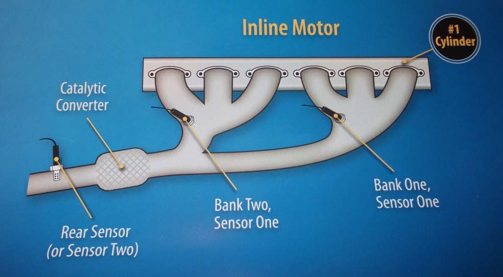
The sensor is capable of producing up to 1 volt with anything over 0.45volts indicating a rich mixture and anything under 0.45volts indicating a lean mixture.
So if we are looking at a pre-cat sensor, the ECU tries to keep the mixture at a LAMBDA of 1 or STOCHIOMETRIC of 14.7:1 which is a reading of about half a volt from the sensor.
Unfortuneatly, narrow band oxygen sensors are not really that accurate once the mixture gets away from that LAMBDA of 1. In fact it is only really accurate from about a LAMBDA of 0.99 - 1.01. Hense the name NARROW BAND sensor.
The signal out of the sensor is not linear so it doesn;t change in direct proportion to the oxygen content.In fact a signal of about 0.15volts is a lambda of 0.99 and a signal of 0.85volts is a lambda of 1.01. Once the mixture gets outside the lambda range the signal voltage is not accurate enough to be useful to the ECU. An air/fuel raio of 12:1, which is very rich only gives a signal of about 0.9volts.
So if you look at the diagram, the signal range of a narrow band sensor looks something like this. Once you get out of this band just either side of a lambda of 1, the sensor is no longer accurate enough to use because a massive change in the mixture only gives a very small change in the voltage.
So what does the ECU do when looking at how much fuel to inject into the engine and how does it use the signal from the oxygen sensor to help?
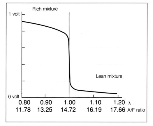
The ECU will increase the injector pulse width until it sees the oxygen sensor signal go above 0.45volts, or rich. Then it will reduce the injector pulse width until it sees the signal go back below 0.45volts, or lean.It will keep on doing this over and over again. This is called CLOSED LOOP operation of the ECU.When you look at the signal generated by the oxygen sensor it should look like this.
Differant manufacturers use differant specifications but the signal should be switching from rich to lean and visa versa around once a second.Falcons switch quite slowly compared to say a Commodore but so long as it is switching at least once a second it should be ok. Also make sure that the voltage is getting up close to 0.9volts and back down to 0.1volts.
Because the narrow band sensor is not able to tell the ECU how rich or how lean the mixture is, the ECU uses closed loop operation, constant switching between rich and lean mixtures to hopefully get an average of the mixtures that is somewhere near a Lambda of 1. It is this inability to know exactly how rich or lean the mixture is that has lead to the use of WIDE BAND or AIR FUEL RATIO sensors because they are able to be used for more exact mixture control.
The ECU will only go into closed loop mode once the oxygen sensor is up to its operating temperature. So before checking the signal you need to make sure that the engine is at operating temperature. If the sensor is a 1 wire or 2 wire then it doesn't have a heater circuit so you will also need to keep the engine revs up at around 2000RPM to ensure there is enough heat being transferred to the sensor. If it is a heated sensor then it should operate at idle. So don't condemn a sensor because you are checking it when it is not up to temperature.
POST-CAT SENSORS
Everything I have referred to up to now has been about the pre-cat sensor operation. Post-cat sensors are normally narrow band sensors and they operate in the same way as the pre-cat narrow band sensors but the ECU uses the signal for a different purpose. The post-cat sensor can also be called the DIAGNOSTIC SENSOR becuase the ECU does not use it for mixture adjustment, only to check on the operation of the CATALYTIC CONVERTOR.
We often get phone calls after someone has replaced a post-cat sensor saying that it is faulty because it is not switching. the problem is that it is not suppossed to be switching. If the post-cat sensor is switching rich-lean like a pre-cat sensor then the catalytic convertor is not working at all, or it is not there anymore.If the catalytic convertor is operating correctly then the post-cat sensor signal should be fairly stable at around 0.4-0.6volts. THE SENSOR SHOULD NOT BE SWITCHING RICH-LEAN. If you stab the throttle or induce a rich mixture then the sensor should read rich and if you back off the throttle or induce a lean mixture then the sensor should read lean but it should not be switching rich-lean-rich-lean. Remember that the only purpose for the post-cat sensor is to monitor the operation of the catalytic convertor.
TITANIUM SENSORS
Titanium sensors are not as widely used as Zirconia sensors but they are out there so it it good to know how they work and how they differ.
Earlier I said that Zirconia sensors work like a battery in that they generate a small voltage in relation to the amount of oxygen present.Titanium sensors don't generate a voltage but instead change resistance in relation to the amount of oxygen present.
So this means that there needs to be a supply voltage to the sensor which passes across the resistor and then goes to the ECU. The voltage that the ECU sees will depend on the changing resistance of the sensor.
The supply voltage is normally 5volts but most ECUs will change the data stream voltage internally so that when you look at live data it will show a voltage that changes from 0.1-0.9volts like a Zirconia type sensor.
The signal works in the same way as a Zirconia sensor in that more than half a volt indicates rich and less than half a volt indicates lean. The benefits of the Titanium sensor over the Zirconia sensor is that they are smaller, they heat up more quickly and are less susceptable to contamination both from pollutents in the exhaust and also from grease and grime on the outside of the sensor. Unlike the Zirconia sensors, Titanium sensors dont need a referance to the outside oxygen to operate so grease and grime dont worry them as much.
TESTING NARROW BAND SENSORS
The most common reason that you will be checking the oxygen sensor operation is because the car has logged a fault code that relates to it. sometimes it might be because the car is running very rich ir lean and you light suspect the sensor as being the cause.
There are a whole bunch of fault codes that can relate to oxygen sensor operation and it is important to note the codes carefully and read the fault description carefully so that you make the right decision when doing your testing.
The fault code should always give you the sensor that is causing the code to log. B1S1, B2S2, B2S1, B2S2.
Some scanners wont give you the whole description, they may only say B1 and not tell you S1 or S2. There are many code books and online resources like the DTC LIBRARY you can download at www.autel.com.au that give you a full description of the code.
The biggest mistake we see is when technicians see a fault code referring to an oxygen sensor and dont do any checks to see if the sensor is the cause of the fault or if there is something causing the sensor to give a signal that is out of spec.
If you have a fault code for a sensor that says it is always reading lean then that could be caused by something as simple as a vacuum leak. Often with emissions related codes they will not re-log the code straight away after it is cleared. It can take some time, may days for the fuel trims to reach there limit and the code to log. Hense the importance of testing the sensor before you just throw a new one in, Surely there is nothing worse than having a customer return with the same fault because you didn't take 15 minutes to test the sensor the first time.
Codes can be broken down into a few groups.
1. SIGNAL FAULTS: RICH/LEAN/SLOW
2. HEATER CIRCUIT
3. CATALYST EFFICIENCY
Signal related codes like alway rich/always lean/slow response need to be tested to see if there is another cause of the signal to be incorrect. If the exhaust mixture is always rich then the sensor will read rich, not becuase it is faulty but because the mixture is actually rich. Some of the things to be checking with mixture related codes are FUEL PRESSURE, VACUUM LEAKS, LEAKING EXHAUSTS, FOULED INJECTORS, IGNITION SYSTEM FAULTS, AIR FLOW METER SIGNALS. If you dont have an exhuast gas analyser, and most workshops dont seem to, then make sure you at least do the opposite to what the sensor is reading to check it's operation. If you have a sensor reading lean all the time then indure a rich mixture by clamping the return line off or spraying in extra fuel supply to see if the sensor responds. If it then reads rich when a rich mixture is induced then it is most likely not the fault. If the sensor is reading rich all the time then induce a lean mixture by creating a large air leak or something similar and see if the sensor responds.
Heater circuit fault codes have become very common in the last few years. This is because the ECUs now monitor this circuit more than they did in older vehicles. The temperature of the sensor is very important to it operating correctly. If you heater circuit fault codes then again there are some checks to be made before the oxygen sensor is deemed to be faulty.
Firstly check the resistance of the heater circuit of the sensor. Narrow band sensors are normally somewhere between 5 and 20 ohms. Most of the time, if the sensor is the original sensor fitted to the car, it will be open circuit if it is faulty. If the sensor has been replaced very recently and youhave a heater curcuit code then the resistance of the replacement sensor may not be correct for the vehicle. The ECU monitors the current draw of the circuit and if it is incorrect because the resistance is 18 ohms instead of 6 ohms then some vehicles will log codes. If the vehicle is a V6 or V8 you can compare the resistance with the sensor on the other bank.They should be the same. You can not compare pre-cat and post-cat sensor resistance as they can be different fro each other.
Secondly you should check that there is a 12volt supply to the heater circuit. The same heater codes will be logged ig the fuse is blown or wiring damaged.Lastly you should check that the ECU is earthing the heater circuit.If there is no earth then the same codes can be logged. In some vehicle the heater circuit will not be held to ground constantly but instead the ECU pulses the earth circuit tp help keep the sensor at the desired temperature. The earth circuit in the ECU can be damaged if the heater circuit of the sensorshorts out and causes too much current to flow to the ECU. So even if you have found that the oxygen sensor heater is faulty you should still check that the ECU is earthing the circuit after it is replaced.
Catalyst efficiency codes can be logged if the post-cat sensor signal is not within specs. The ECU will monitor the signal and if it is too low,too high, or is swithcing, then the ECU will log a code. You should check the sensor signal in the same way as you would a pre-cat narrow band sensor. If the sensor is responding to induced rich and or lean mixtures then the sensor is most likely OK. The catalytic convertor may not be working correctly, which is what the sensor is designed to monitor. We also see many catalyst efficiency codes being loggedwhen aftermarket cats are fitted to cars. Some cars have very tight specifications and fitting high flow cats or even standard aftermarket cats can be problematic if it is not matched to the vehicle correctly. BF-FG Falcons and VZ-VE Commodoresare some of the most common vehicles we have seen this happen on.
REMEMBER: OXYGEN SENSOR FAULT CODES DON'T ALWAYS MEAN THE SENSOR IS FAULTY!!!!!
FUEL TRIMS
Fuel Trims are something that most workshops overlook when they are looking at oxygen sensor issues or even just running rough or excess fuel usage. They can be very helpful when checking a vehicle for these types of issues.
An ECU has a bunch of fuel maps stored in its memory and it will change between different maps depending on the conditions it sees. There can be set maps for when the vehicle is say, under full acceleration or under decel or when the engine is cold, but most of the time the ECU will be in CLOSED LOOP MODE, looking at the feedback from the pre-cat oxygen sensor to determine if the correct fuel mixture is being used.
There are 2 types of fuel trims, SHORT TERM and LONG TERM.Short term fuel trim is what the ECU is doing right now and Long term fuel trim is what has been happening in the past. In older vehicles there were a few different ways that the fuel trims were indicated on the scan tool depending on the make of the vehicle but with newer vehicles they all use a common method to display the data.
The base fuel trim that the vehicle will start with is '0'. In closed loop mode the ECU willmonitor the oxygen sensor operation and if it is switching from rich to lean correctly then it will stay on this fuel trim. If the oxygen sensor is always reading rich then the ECU will move to a leaner map. On the scan tool it will read '-1', meaning that the fuel map is now 1% leaner than the '0' fuel map.If the oxygen sensor still reads rich for a period of time then the fuel trim will move to '-2'. The ECU will keep doing this until either then sensor starts to switch or the limit of the ECUs map is reached, which is normally -25 or 25% leaner than its base map.The same operation happens if the oxygen sensor is always reading lean except that the ECU will move to a '+1' map and so on up to '+25'. If the ECU reaches its limit of adjustment then that is when it will log a fault code.
So if you were to look at a vehicle where the customer was complaining of high fuel consumption you can see how the fuel trim data could be useful. When looking at the oxygen sensor it may very well be switching rich to lean as you wouldlike but if you look at the long term fuel trim and it is reading a richer than normal fuel map to get the sensor to switch, this would indicate that something is leaning out the mixture and the ECU is having to add more fuel to get the sensor to switch.This could be a small air leak or an air flow meter not reading accurately or anything else that can lean out the mixtures.
The fuel trims cam move away from the ideal '0' under normal conditions due to things like the weather, atmospheric pressure and the like, but if they are more than about 10% richer or leaner then it is something that should be checked further.


